Glossary
The Kraus & Naimer product portfolio includes numerous switching devices as well as optional extras for the low-voltage range and offers switching solutions for a wide variety of individual requirements. This glossary explains the most common terms associated with switching technology and switching devices from Kraus & Naimer.
Content
1. General and technical terms
1.1 Low voltage
1.2 AC
1.3 DC
1.4 Switch
1.5 Switching contact
1.6 Switching arc
1.7 Arc quenching
1.8 Bridge contact
1.9 Blade contact
2. Types of switches and products
2.1 Disconnectors
2.2 Load switches
2.3 Switch-disconnectors
2.4 Directly operated switches
2.5 Rotary switches
2.6 Cam switches
2.7 Main switches (compact switches)
2.8 Optional extras
2.9 Push buttons and pilot lights
1.2 AC
Alternating voltage or alternating current (AC) means that the respective voltage and current values change with time and periodically reverse. In electrical engineering, primarily sinusoidal alternating voltages and currents are applied. Each cycle of the voltage includes two zero-crossings during which the current strength and direction change. In a common 50 Hz low-voltage grid the voltage reverses itself 50 times per second and thus 100 zero crossings occur when momentary no current flows. This characteristic of AC circuits is advantageous for switching operations.
1.3 DC
Direct voltage or direct current (DC) means that the voltage polarity and current direction remain the same over time. In contrast to AC, electrical current flows continuously without direction alternation and therefore no zero crossings occur. As a result, switching operations in DC circuits are more technically demanding than in AC circuits due to longer switching arc duration, which leads to increased wear of the switching contacts.
1.4 Switch
A switch is an assembly within an electrical circuit that either makes or breaks the flow of current and maintains the respective switching state. Switches are manufactured in numerous designs with specific functions for a wide variety of purposes. Essential components of a mechanical switching device are the switching contacts made of conductive materials or suitable metals and alloys. The switching contacts are actuated and held in their respective switching position by special mechanical constructions.
1.5 Switching contact
A switching contact directly establishes the physical connection between contact pieces in order to close a circuit. To counteract the occurring electrodynamic forces that cause the contact pieces to repel, an adequate contact force is necessary, especially in case of overcurrent. Switching contacts are exposed to high mechanical, electrical, and thermal stress and must maintain their function for a large number of switching cycles. Especially the switching arc, which occurs by interrupting an electrical circuit, substantially causes wear of a switching device.
1.6 Switching arc
A switching arc is a phenomenon that occurs under certain conditions when current-carrying electrical contacts are disconnected. The switching arc is very pronounced when inductive loads, such as electric motors, are interrupted. An inductive load stores energy in the form of a magnetic field. The energy stored in the magnetic field causes the continuation of current flow through an arc, after current interruption. The arc persists until reaching a sufficient separation distance of the contacts or until the arc and its temperature dissipate the magnetic energy. The arc temperature reaches several thousand ° C and therefore a switching arc has a destructive effect and causes wear. Contact materials liquefy on the surface due to the high temperature and this may lead to contact welding.
1.7 Arc quenching
To minimize arc duration while breaking an electrical circuit, additional design features are implemented to effectively extinguish the arc. One example of a possible design feature is the so-called spark quenching chamber, which uses metal sheets to separate and cool the arc that furthermore leads to rapid energy dissipation. Another possibility is the use of special outgassing plastics. The temperature of the arc releases gas from the plastic walls of the switching chamber, which consequently causes an intensive arc cooling and energy absorbing effect.
Permanent magnets are used to effectively guide the arc into the quenching device or area, especially in switches for DC circuits. Since an electric arc is also a current-carrying conductor with a magnetic field, it is deflected by the permanent magnets.
In addition to the above-mentioned arc quenching possibilities, an extension of the isolating distance and a fast breaking operation are beneficial for direct current. The overall isolating distance can be extended by the serial connection of multiple contacts that are actuated simultaneously, whereby the necessary isolating distance is divided among multiple contact interruptions. To reach the isolating distance as quickly as possible, snap-action mechanisms are used for rapid contact breaking.
1.8 Bridge contact
A bridge contact consists of a movable contact bridge and two fixed contact pieces. The switching mechanism moves the contact bridge onto the contact pieces and applies a determined contact force. The rigid contact bridge interrupts the electrical circuit twice. The isolation distance is twice of the determined contact travel distance.
1.9 Blade contact
A blade contact consists of flexible contact springs and a switchblade, whereby the switchblade is inserted between several contact springs to make contact. Due to the sliding shear movement between the switchblade and the contact springs, the contact surfaces are self-cleaning with each actuation, this way deposit and corroded layers are removed. In addition to the self-cleaning characteristic, this contact system is more resistant against vibrations and electrodynamic repelling forces in comparison to conventional contact systems.
2. Types of switches and products
2.1 Disconnectors
Disconnectors are mechanical switching devices that separate equipment or plant components from a power supply system. Disconnectors must have sufficiently large isolating distances or clearances and creepage distances to prevent unintentional start-ups, for example in the event of overvoltage waves or dirty creepage paths. Disconnect switches are not intended to switch currents and are only operated after circuits have already been interrupted by other devices, such as circuit breakers, load switches or fuses.
A disconnector can open and close a circuit when either only a negligible current is switched off or on, or when no significant voltage change occurs between the terminals of each disconnector pole. It can carry current continuously under operating conditions and for a specified time under exceptional conditions such as short circuit.
2.2 Load switches
In contrast to disconnectors, load switches are suitable for switching current-carrying equipment and system parts under normal circumstances with the intended operating current. Since these switches are operated under load and switching arcs can occur, they include various design measures for arc quenching.
2.3 Switch-disconnectors
Switch-disconnectors combine the functions of load switches and disconnectors. Switch-disconnectors therefore fulfill the isolating functions – such as appropriately dimensioned clearances and creepage distances as well as switching status indication – and furthermore provide determined switching capacities. The switching capacity generally refers to the ability to break current flow, whereby the switching capacity of a switching device differs depending on the load type. The different load types are standardized and assigned to different utilization categories. A utilization category contains a combination of several requirements that a corresponding switching device must comply with.
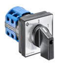
2.5 Rotary switches
Rotary switches are generally actuated by a turning operation. The switching mechanism transmits the rotary operation motion to the moving parts of the switching contacts. Rotary switches can provide multiple switching positions and operate several circuits differently with a single device, depending on the actual switch design.
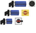
2.6 Cam switches
Cam switches count as rotary operated switches. The rotary operation motion is transmitted by cams to actuate the switching contacts. A single cam can actuate multiple switching contacts differently within geometric boundaries. The modular design of Kraus & Naimer cam switches allows the stacking of multiple switching stages as well as extensions with numerous optional extras. Due to this modularity, mechanical switching devices are configurable for countless applications. Simple single-pole and multi-pole on/off switches, changeover switches, multistep switches, motor switches or control switches as well as many other circuits can be realized with the modular portfolio.
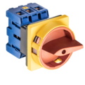
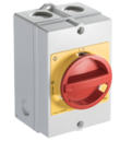
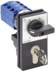
2.7 Main switches (compact switches)
The purpose of main switches is the connection or disconnection of plant components, various equipment or machinery with the power supply. An especially compact design has been established for main switches in which the three poles of a three-phase AC supply are switched simultaneously. Furthermore, four-pole designs also exist for applications where the neutral line is switched, whereby the neutral pole functions as early-make/late-break contact. Main switches are switch disconnectors with high switching capacities in relation to their size. The compact main switches from Kraus & Naimer feature positive contact movement during making or breaking operation. In addition, the main/compact switches are embedded in an extensive modular system with numerous functional expansions and optional extras.
2.8 Optional extras
The optional extras are a part of the comprehensive modular system from Kraus & Naimer and enables a wide variety of functional extensions for our switchgear devices. The modular system includes numerous variants of padlock devices, key lock devices, door clutches, various enclosures as well as solutions for special applications, such as various indicator devices, interlock devices or special drives.
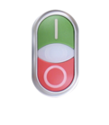
2.9 Push buttons and pilot lights
Push buttons and pilot lights are input and output devices to operate machinery and to receive feedback on various machine states. Push buttons and switches with low switching capacity or potentiometers are used as command devices and serve as electrical signal transmitters for control units. Pilot lights serve as optical signaling devices for machine operators. Combinations of push buttons and pilot lights within one device are available as well and the extensive range of the Kraus & Naimer product portfolio offers solutions for a wide variety of applications.