Info
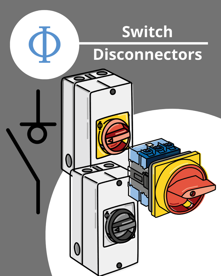
Switch Disconnectors - Functions and Requirements

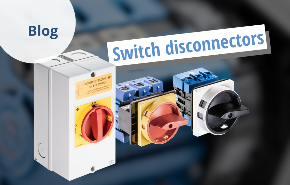
Switch disconnectors from Kraus & Naimer provide a reliable and safe solution for switching and isolating electrical currents across a wide range of applications. They meet all relevant standards and combine two essential functions: load switching and safe electrical isolation, ensuring optimum performance and maximum safety.
What is a Switch Disconnector?
Switch disconnectors are key components of electrical installations. They combine the operational capacity of a switch with the safety function of an isolator. They are designed to:
- Safely make, carry and break electrical currents under normal operating conditions
- Withstand overload and short-circuit conditions for a defined duration, depending on the design.
A mechanical switch disconnector is a device capable of making, carrying and breaking currents under normal conditions (including specified operational inrush currents), and of carrying currents for a defined time under abnormal overcurrent conditions such as short circuits. When in the open position, it meets the full requirements of an isolating device.
Electrical Characteristics
As mechanical switching devices, switch disconnectors are designed to operate reliably under normal load conditions as well as during overload and short-circuit events. Key characteristics include:
- Switching capacity: The ability to switch live currents depends on the load case and is defined by the applicable standards.
- Isolating function: In the open position, the switch disconnector fulfills all requirements of an isolator, including the specified air and creepage distances as well as a clear and unambiguous indication of the switching position.
Normative Requirements
In order to be recognized as devices with isolating capability, switch disconnectors must comply with strict normative requirements. These include:
Isolating distance: In the open position, a defined isolating distance must be provided in accordance with the relevant standards.
Switch position indication: The position of the main contacts must be indicated by one or more of the following methods:
- Position of the operating handle (this is the primary indication used by Kraus & Naimer)
- Separate mechanical indicator (used by Kraus & Naimer particularly for door-coupling solutions)
- Visibility of all moving main contacts
Mechanical strength: The effectiveness and mechanical robustness of the indicating mechanisms must be verified.
Interlocking: If interlocking in the open position is provided, it must only be possible when the main contacts are truly open.
Mounting: Handle, front plates and covers must ensure correct indication and reliable interlocking at all times.
Switch Disconnectors in Practice
Switch disconnectors are used in a wide variety of applications and are therefore available in various designs. Terminology varies in practice, which can sometimes lead to confusion. The following examples illustrate common applications and naming conventions.
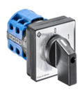
As Main Switches
In machines or other system components, switch disconnectors are used as main switches. They are often equipped with a locking device that allows the switch to be locked in the 0 or OFF position, ensuring safe isolation during downtime.
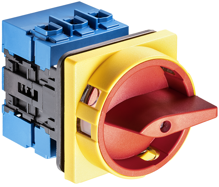
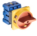
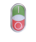
As Emergency Off Switches
Emergency off switches are a type of main switch (power supply disconnecting devices according to EN 60204‑1) that must feature a red operatinghandle and a yellow background for visibility and safety.
Activating the emergency off switch, disconnects the power supply immediately, preventing electrical hazards.
They are intended for foreseeable or exceptional hazardous situations that may require quick external intervention.

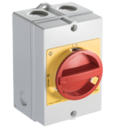
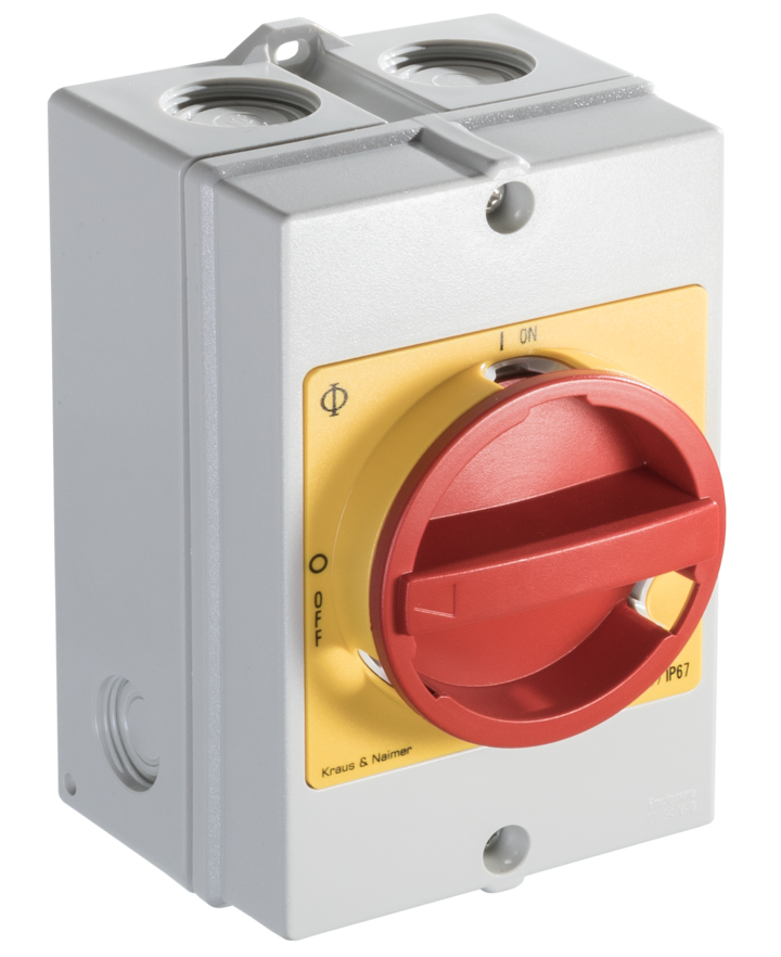
As Enclosed Switch Disconnectors according to EN 62626-1
Enclosed switch disconnectors outside the scope of IEC 60947‑3, intended for isolation during repair or maintenance work, are switches with an integrated locking device housed in an enclosure that comply with EN 62626‑1.
These devices are referred to as Safety Switches.
Compliant products bear a standard identification symbol; the label colour is not prescribed, though orange is widely used.
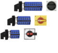
As Repair and Maintenance Switches
This term is commonly used to describe switch disconnectors or main switches - often with an emergency stop function - installed in an enclosure.
This designation reflects their frequent use during repair, maintenance and cleaning operations. In these applications, the switch is locked in the OFF position using a padlock to prevent machines and systems from being accidentally switched on during servicing or cleaning work.
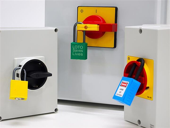
Requirements related to Locking Devices
As already mentioned, switch disconnectors equipped with locking devices are frequently used as enclosed switch disconnectors in accordance with EN 62626‑1. In this case, the interlocking mechanism must be designed in such a way that it cannot be removed while the relevant padlocks are applied.
Even if the device is locked using only a single padlock, it must not be possible -by actuating the operating handle - to reduce the air gap between open contacts to such an extent that the requirements of the applicable standard are no longer fulfilled.
Alternatively, a padlockable protective device may block access to the handle entirely.
Application Examples
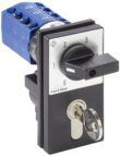
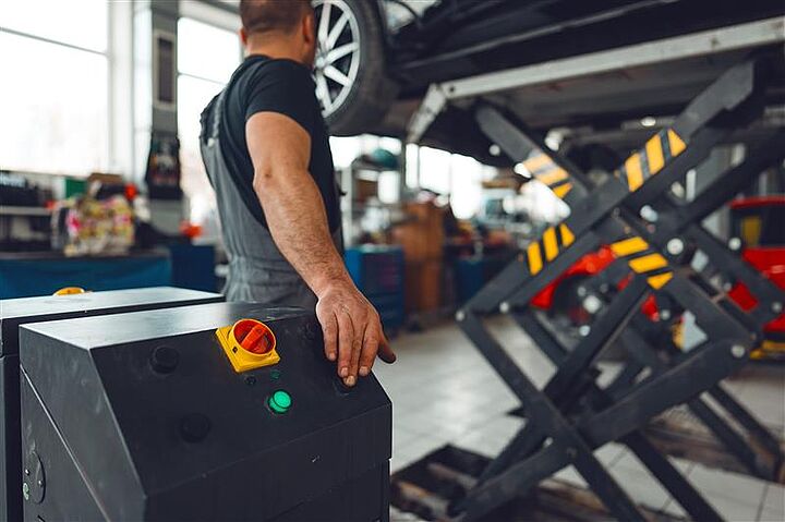
Main Switches for Vehicle Lifting Platforms
A practical example is a vehicle lifting platform in an automotive workshop.
The system is equipped with a switch disconnector functioning as the main switch, as well as a motor switch designed as a motor reversing switch to control up/down movement of the platform.
Electromagnetic Compatibility (EMC)
When switch disconnectors used as repair and maintenance switches are installed in plastic enclosures with high mechanical strength and high UV resistance, EMC accessories from Kraus & Naimer help protect sensitive electronics from electromagnetic interference.
Thanks to EMC‑compliant design, the generation and propagation of electromagnetic disturbances are minimized. This is particularly important when variable frequency drives (VFDs) are used.
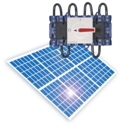
Variable frequency drives are commonly used to control motor speeds in production facilities and building technology applications, such as regulating pumps and fans. In wind and solar power plants, VFDs also help feed generated energy efficiently into the electrical grid.
Explosive Atmospheres – Zone 21 & Zone 22
To prevent ignitions caused by sparking during the operation of switch disconnectors used as repair and maintenance switches, enhanced safety requirements must be met. Kraus & Naimer offers switch disconnectors in accordance with the ATEX Directive that are suitable for use in Zone 21 and Zone 22.
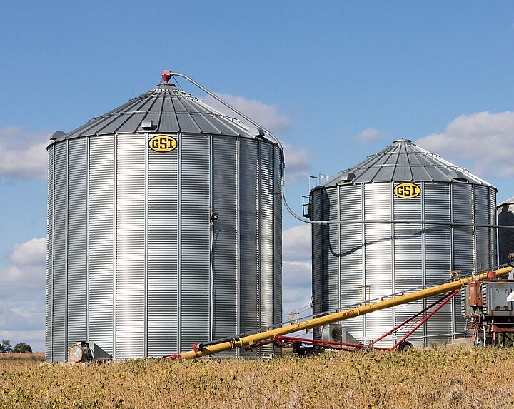
In industries such as food and animal feed production - particularly in silo installations - combustible dusts may form in various areas.

When these dusts are sufficiently fine and present at a minimum concentration, mixed with oxygen in the air, they can create an explosive atmosphere (ATEX: ATmosphère EXplosive).
If ignited, it may lead severe injury and major property damage.